Control & Algorithm
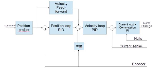
Our basic motion algorithm is based on cascaded Position Velocity and Torque.
Each control loop has its PID, integral anti windup, low-pass filter, feed-forward, adaptive gains.
Current loop implemented in Space-Vector and D-Q control.
Engineering units are used - RPM, Ampere, Volt, RPM/Sec etc. if required customer units could be translated.
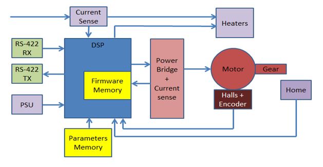
The entire control is written in C and could easily be changed and adapted according to project needs.
We are open to changes - each part of the algorithm could be changed or adapted according to the specific control requirements of the system.
We are open to embed part or entire machine control, firmware and algorithm in the motor control processor or add another processor for those needs.

Hardware Capabilities
We are open to any challenging design, our previous designs includes:
Motor type:
- DC
- BLDC / PMSM (Sinusoidal or Trapezoidal)
- Stepper
- Voice coil
- Piezo
Motor:
- Voltages - from 3V up-to 1200V (and more..)
- Currents - from few milli-Ampers to hundreds of Ampers
- from milli-Watts to tens of KWatts
- Halls only
- Quadrature encoders
- Absolut encoders
Communication:
- ASCII based UART (RS-232, RS-422, RS-485)
- CanOpen
- EtherCAT - ETG Member
- Analog
- Servo type PWM
I/O:
- Standard digital I/O
- Fast capture input
- Position capture
- 4-20mA
- 0-10V
- Quadrature input
- Pulse & Direction
- Servo PWM
- and much more
- Use of EtherCAT I/O for special purpose system functionality
- Unlimited number of encoder emulation channels over EtherCat

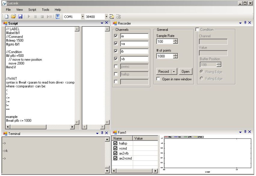
Drive GUI - GaLink
The GaLink is technician level Windows GUI that is used for:
- Parameters download
- Scripts launch
- Record drive performance
- Servo loop tuning
- etc.
The GaLink connects to the drive via UART and use ASCII protocol.
